

Introduction
Some of my notes on describing how to add rs485 to a Beaglebone Black’s uart4 interface and enable terminal login.
rs485 is very handy when it comes to communicating with industrial systems over modbus-rtu.
Bill of goods
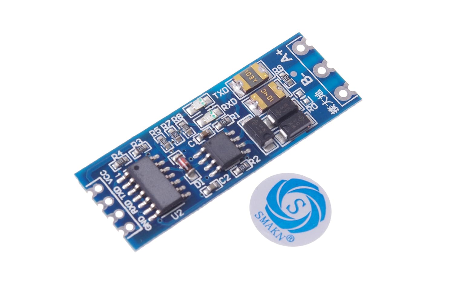
- ttl to rs485 adapter ttl-rs485
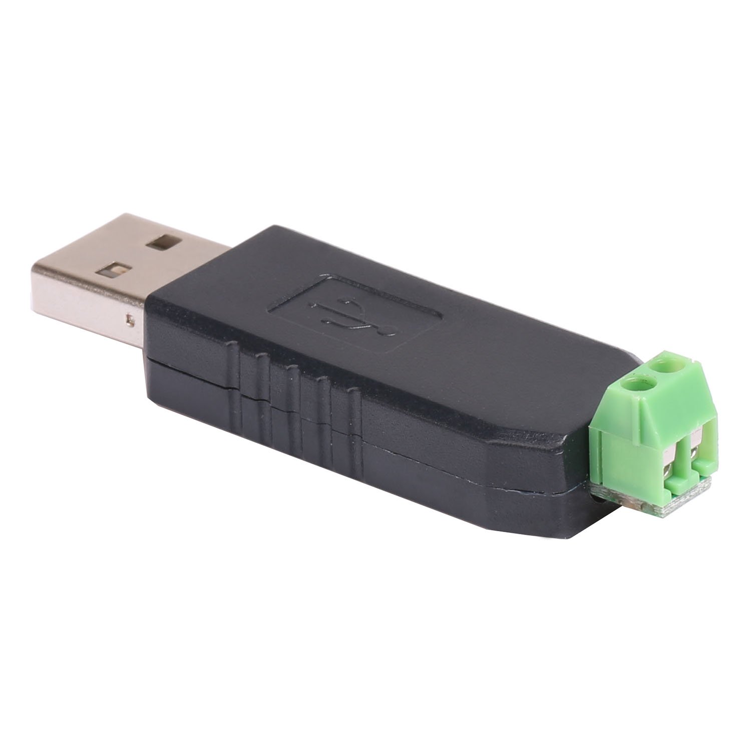
- usb to rs485 usb-rs485
Wiring up
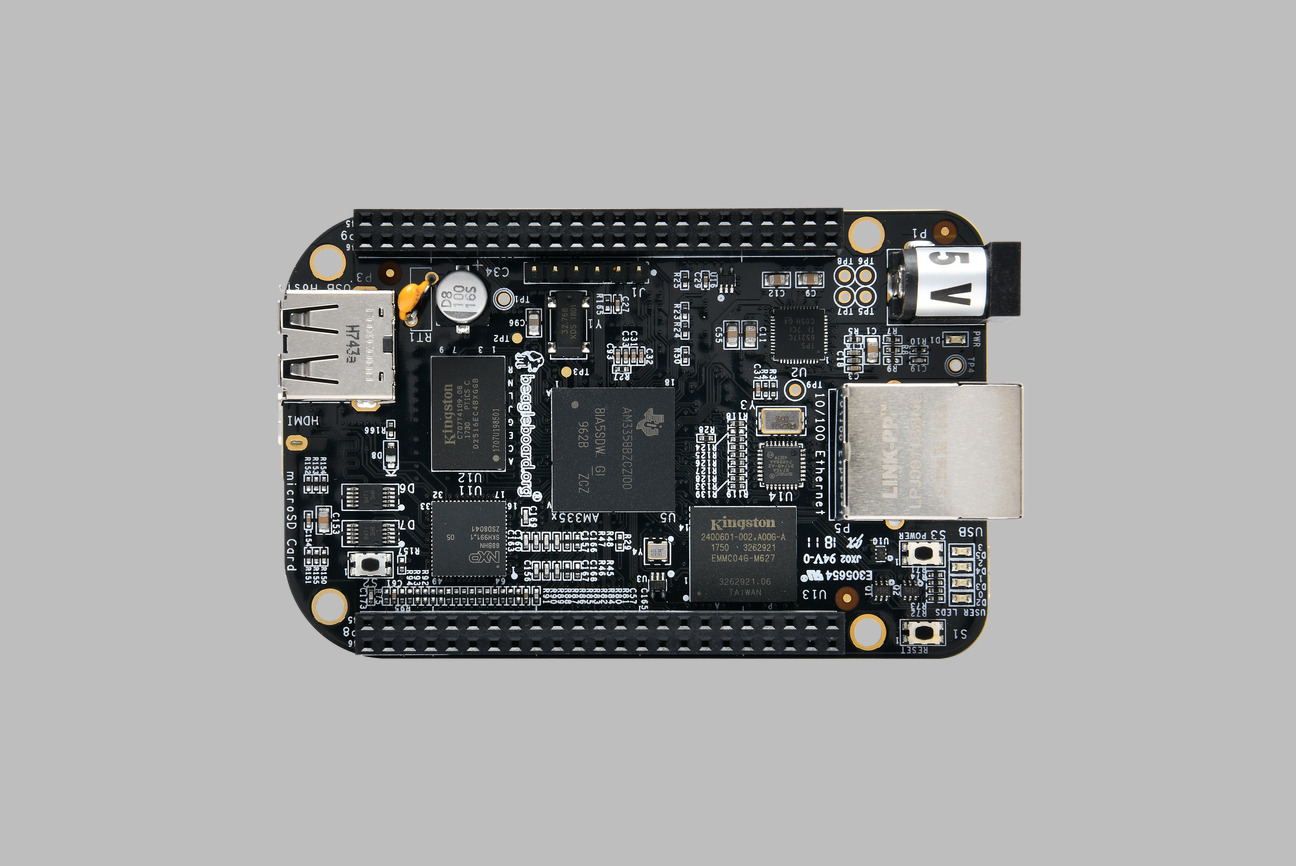
Beaglebone
- p9-pin1-gnd -> ttl-rs485 gnd
- p9-pin2-gnd -> ttl-rs485 gnd
- p9-pin3-vcc -> ttl-rs485 vcc
- p9-pin11-uart4_rxd -> ttl-rs485-rxd
- p9-pin13-uart4_txd -> ttl-rs485-txd
PC
- usb-rs485-A -> ttl-rs485-A
- usb-rs485-B -> ttl-rs485-B
Configure Beaglebone
I have a custom kernel and dtb configured for my bbb.
At present my kernel version is
$ uname -a

Linux buildroot 4.9.1-00002-gcc864a08bcb4-dirty #0 SMP Sat Jan 7 23:43:44 PST 2017 armv7l GNU/Linux
This is a copy of my custom dtb to enable uart4
am335x-customboneblack.dts
/*
 * Copyright (C) 2012 Texas Instruments Incorporated - http://www.ti.com/
 *
 * This program is free software; you can redistribute it and/or modify
 * it under the terms of the GNU General Public License version 2 as
 * published by the Free Software Foundation.
 */
/dts-v1/;

#include "am33xx.dtsi"
#include "am335x-bone-common.dtsi"
#include <dt-bindings/display/tda998x.h>

/ {
 model = "TI AM335x BeagleBone Black";
 compatible = "ti,am335x-bone-black", "ti,am335x-bone", "ti,am33xx";
};

&ldo3_reg {
 regulator-min-microvolt = <1800000>;
 regulator-max-microvolt = <1800000>;
 regulator-always-on;
};

&mmc1 {
 vmmc-supply = <&vmmcsd_fixed>;
};

&mmc2 {
 vmmc-supply = <&vmmcsd_fixed>;
 pinctrl-names = "default";
 pinctrl-0 = <&emmc_pins>;
 bus-width = <8>;
 status = "okay";
};

&am33xx_pinmux {

/* Pins 21 (TX) and 22 (RX) of connector P9 */
 uart2_pins: uart2_pins {
 pinctrl-single,pins = <
 AM33XX_IOPAD(0x954, PIN_OUTPUT_PULLDOWN | MUX_MODE1) /* spi0_d0.uart2_tx */
 AM33XX_IOPAD(0x950, PIN_INPUT_PULLUP | MUX_MODE1) /* spi0_sclk.uart2_rx */
 >;
 };

/* Pins 11 (RX) and 13 (TX) of connector P9 */

uart4_pins: uart4_pins {
 pinctrl-single,pins = <
 AM33XX_IOPAD(0x870, PIN_INPUT_PULLUP | MUX_MODE6) /* gpmc_wait0.uart4_rx */
 AM33XX_IOPAD(0x874, PIN_OUTPUT_PULLDOWN | MUX_MODE6) /* gpmc_wpn.uart4_tx */
 >;
 };

nxp_hdmi_bonelt_pins: nxp_hdmi_bonelt_pins {
 pinctrl-single,pins = <
 AM33XX_IOPAD(0x9b0, PIN_OUTPUT_PULLDOWN | MUX_MODE3) /* xdma_event_intr0 */
 AM33XX_IOPAD(0x8a0, PIN_OUTPUT | MUX_MODE0) /* lcd_data0.lcd_data0 */
 AM33XX_IOPAD(0x8a4, PIN_OUTPUT | MUX_MODE0) /* lcd_data1.lcd_data1 */
 AM33XX_IOPAD(0x8a8, PIN_OUTPUT | MUX_MODE0) /* lcd_data2.lcd_data2 */
 AM33XX_IOPAD(0x8ac, PIN_OUTPUT | MUX_MODE0) /* lcd_data3.lcd_data3 */
 AM33XX_IOPAD(0x8b0, PIN_OUTPUT | MUX_MODE0) /* lcd_data4.lcd_data4 */
 AM33XX_IOPAD(0x8b4, PIN_OUTPUT | MUX_MODE0) /* lcd_data5.lcd_data5 */
 AM33XX_IOPAD(0x8b8, PIN_OUTPUT | MUX_MODE0) /* lcd_data6.lcd_data6 */
 AM33XX_IOPAD(0x8bc, PIN_OUTPUT | MUX_MODE0) /* lcd_data7.lcd_data7 */
 AM33XX_IOPAD(0x8c0, PIN_OUTPUT | MUX_MODE0) /* lcd_data8.lcd_data8 */
 AM33XX_IOPAD(0x8c4, PIN_OUTPUT | MUX_MODE0) /* lcd_data9.lcd_data9 */
 AM33XX_IOPAD(0x8c8, PIN_OUTPUT | MUX_MODE0) /* lcd_data10.lcd_data10 */
 AM33XX_IOPAD(0x8cc, PIN_OUTPUT | MUX_MODE0) /* lcd_data11.lcd_data11 */
 AM33XX_IOPAD(0x8d0, PIN_OUTPUT | MUX_MODE0) /* lcd_data12.lcd_data12 */
 AM33XX_IOPAD(0x8d4, PIN_OUTPUT | MUX_MODE0) /* lcd_data13.lcd_data13 */
 AM33XX_IOPAD(0x8d8, PIN_OUTPUT | MUX_MODE0) /* lcd_data14.lcd_data14 */
 AM33XX_IOPAD(0x8dc, PIN_OUTPUT | MUX_MODE0) /* lcd_data15.lcd_data15 */
 AM33XX_IOPAD(0x8e0, PIN_OUTPUT_PULLDOWN | MUX_MODE0) /* lcd_vsync.lcd_vsync */
 AM33XX_IOPAD(0x8e4, PIN_OUTPUT_PULLDOWN | MUX_MODE0) /* lcd_hsync.lcd_hsync */
 AM33XX_IOPAD(0x8e8, PIN_OUTPUT_PULLDOWN | MUX_MODE0) /* lcd_pclk.lcd_pclk */
 AM33XX_IOPAD(0x8ec, PIN_OUTPUT_PULLDOWN | MUX_MODE0) /* lcd_ac_bias_en.lcd_ac_bias_en */
 >;
 };
 nxp_hdmi_bonelt_off_pins: nxp_hdmi_bonelt_off_pins {
 pinctrl-single,pins = <
 AM33XX_IOPAD(0x9b0, PIN_OUTPUT_PULLDOWN | MUX_MODE3) /* xdma_event_intr0 */
 >;
 };

mcasp0_pins: mcasp0_pins {
 pinctrl-single,pins = <
 AM33XX_IOPAD(0x9ac, PIN_INPUT_PULLUP | MUX_MODE0) /* mcasp0_ahcklx.mcasp0_ahclkx */
 AM33XX_IOPAD(0x99c, PIN_OUTPUT_PULLDOWN | MUX_MODE2) /* mcasp0_ahclkr.mcasp0_axr2*/
 AM33XX_IOPAD(0x994, PIN_OUTPUT_PULLUP | MUX_MODE0) /* mcasp0_fsx.mcasp0_fsx */
 AM33XX_IOPAD(0x990, PIN_OUTPUT_PULLDOWN | MUX_MODE0) /* mcasp0_aclkx.mcasp0_aclkx */
 AM33XX_IOPAD(0x86c, PIN_OUTPUT_PULLDOWN | MUX_MODE7) /* gpmc_a11.GPIO1_27 */
 >;
 };
};

&lcdc {
 status = "okay";
 port {
 lcdc_0: endpoint@0 {
 remote-endpoint = <&hdmi_0>;
 };
 };
};

&i2c0 {
 tda19988: tda19988 {
 compatible = "nxp,tda998x";
 reg = <0x70>;

pinctrl-names = "default", "off";
 pinctrl-0 = <&nxp_hdmi_bonelt_pins>;
 pinctrl-1 = <&nxp_hdmi_bonelt_off_pins>;

#sound-dai-cells = <0>;
 audio-ports = < TDA998x_I2S 0x03>;

ports {
 port@0 {
 hdmi_0: endpoint@0 {
 remote-endpoint = <&lcdc_0>;
 };
 };
 };
 };
};

&uart2 {
 status = "okay";
 pinctrl-names = "default";
 pinctrl-0 = <&uart2_pins>;
};

&uart4 {
 status = "okay";
 pinctrl-names = "default";
 pinctrl-0 = <&uart4_pins>;
};

&rtc {
 system-power-controller;
};

&mcasp0 {
 #sound-dai-cells = <0>;
 pinctrl-names = "default";
 pinctrl-0 = <&mcasp0_pins>;
 status = "okay";
 op-mode = <0>; /* MCASP_IIS_MODE */
 tdm-slots = <2>;
 serial-dir = < /* 0: INACTIVE, 1: TX, 2: RX */
 0 0 1 0
 >;
 tx-num-evt = <32>;
 rx-num-evt = <32>;
};

/ {
 clk_mcasp0_fixed: clk_mcasp0_fixed {
 #clock-cells = <0>;
 compatible = "fixed-clock";
 clock-frequency = <24576000>;
 };

clk_mcasp0: clk_mcasp0 {
 #clock-cells = <0>;
 compatible = "gpio-gate-clock";
 clocks = <&clk_mcasp0_fixed>;
 enable-gpios = <&gpio1 27 0>; /* BeagleBone Black Clk enable on GPIO1_27 */
 };

sound {
 compatible = "simple-audio-card";
 simple-audio-card,name = "TI BeagleBone Black";
 simple-audio-card,format = "i2s";
 simple-audio-card,bitclock-master = <&dailink0_master>;
 simple-audio-card,frame-master = <&dailink0_master>;

dailink0_master: simple-audio-card,cpu {
 sound-dai = <&mcasp0>;
 clocks = <&clk_mcasp0>;
 };

simple-audio-card,codec {
 sound-dai = <&tda19988>;
 };
 };
};
Attached getty to ttyO4
$ cat /etc/inittab
# /etc/inittab
#
# Copyright (C) 2001 Erik Andersen <andersen@codepoet.org>
#
# Note: BusyBox init doesn't support runlevels. The runlevels field is
# completely ignored by BusyBox init. If you want runlevels, use
# sysvinit.
#
# Format for each entry: <id>:<runlevels>:<action>:<process>
#
# id == tty to run on, or empty for /dev/console
# runlevels == ignored
# action == one of sysinit, respawn, askfirst, wait, and once
# process == program to run

# Startup the system
null::sysinit:/bin/mount -t proc proc /proc
null::sysinit:/bin/mount -o remount,rw / # REMOUNT_ROOTFS_RW
null::sysinit:/bin/mkdir -p /dev/pts
null::sysinit:/bin/mkdir -p /dev/shm
null::sysinit:/bin/mount -a
null::sysinit:/bin/hostname -F /etc/hostname
# now run any rc scripts
::sysinit:/etc/init.d/rcS

# Put a getty on the serial port
ttyO0::respawn:/sbin/getty -L ttyO0 115200 vt100 # GENERIC_SERIAL
ttyO2::respawn:/sbin/getty -L ttyO2 115200 vt100 # GENERIC_SERIAL
ttyO4::respawn:/sbin/getty -L ttyO4 115200 vt100 # GENERIC_SERIAL

# Stuff to do for the 3-finger salute
::ctrlaltdel:/sbin/reboot

# Stuff to do before rebooting
null::shutdown:/etc/init.d/rcK
null::shutdown:/bin/umount -a -r
null::shutdown:/sbin/swapoff -a
Needless to say that one must compile the new dtb and place onto the bbb. How to do this is out of the scope of this doc but I’ve included a reference to free-electron’s fantastic tutorial on how to do it.
Test
From my PC I connect the usb-rs485 adapter and open a terminal to it
$ ls /dev/tty.w*
/dev/tty.wchusbserial1a1210

$ screen /dev/tty.wchusbserial1a1210 115200

Welcome to Buildroot
buildroot login: remote
Password:
$ uname -a
Linux buildroot 4.9.1-00002-gcc864a08bcb4-dirty #0 SMP Sat Jan 7 23:43:44 PST 2017 armv7l GNU/Linux
Seems easy but I spent a while trying out different ttl-rs485 modules for the bbb and failed. This one worked flawlessly without an extra pins for cts/dts, re/de.
References
Free Electrons training on Linux development and device drivers
